Product: Abaqus/Standard
C3D4 C3D6 C3D8 C3D10 C3D10M C3D15 C3D20
CCL9 CCL12 CCL18 CCL24
Contact between a deformable body and a rigid surface and contact between two deformable surfaces exposed to a fluid pressure at both ends of the surfaces are tested through the use of pressure penetration loads.
Material:
Young's modulus = 1 × 10⁵; Poisson's ratio = 0.3.
Boundary conditions:
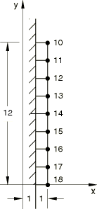
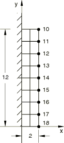
Two-dimensional models: The rigid surface is constrained in all degrees of freedom. When the contact between two deformable surfaces is considered, the nodes at ![]() 0 in Figure 1.3.43–2 and the nodes at
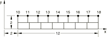
0 in Figure 1.3.43–2 and the nodes at ![]() 0 in Figure 1.3.43–3 are constrained in all degrees of freedom.
0 in Figure 1.3.43–3 are constrained in all degrees of freedom.
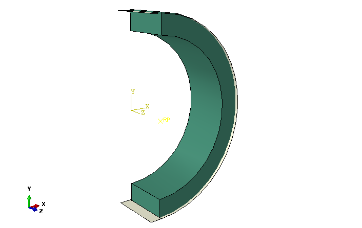
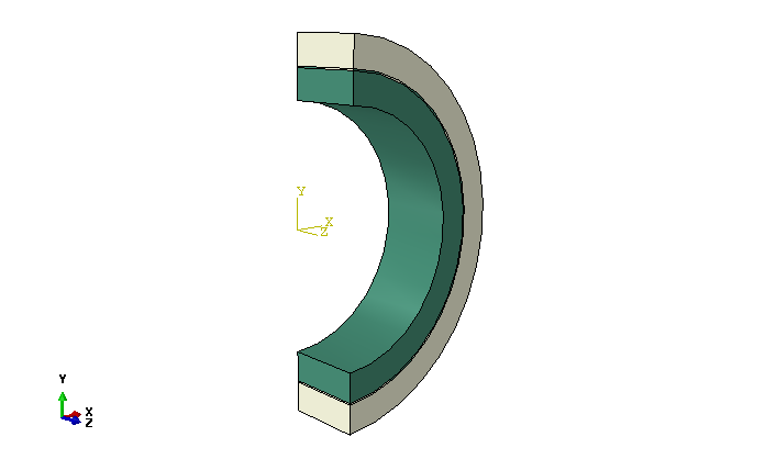
Three-dimensional models (Figure 1.3.43–4 and Figure 1.3.43–5): The rigid surface is constrained in all degrees of freedom. The nodes at the two ends of the rings are constrained in the first degree of freedom, and the nodes at the back surfaces are constrained in the third degree of freedom; when the contact between two deformable surfaces is considered, the inner and outer ring surfaces of the model are also constrained in all degrees of freedom.
Loading:
For the two-dimensional models illustrated in Figure 1.3.43–1 and Figure 1.3.43–2:
Step 1: A nonuniform displacement, ![]() , is applied in the negative x-direction on the surface of
, is applied in the negative x-direction on the surface of ![]() 2.0 when solid elements are used.
2.0 when solid elements are used. ![]() is the displacement at node 14, and d is the distance measured from node 14. When shell elements are used, a nonuniform pressure,
is the displacement at node 14, and d is the distance measured from node 14. When shell elements are used, a nonuniform pressure, ![]() , is applied on the surface of
, is applied on the surface of ![]() 2.0.
2.0. ![]() is the pressure at the element containing node 14, and
is the pressure at the element containing node 14, and ![]() is the distance measured from node 14 to the center of an element.
is the distance measured from node 14 to the center of an element.
Step 2: Two ends of the contacting surfaces (![]() 0 and
0 and ![]() 12.0) are exposed to a fluid pressure with a magnitude of 800.0.
12.0) are exposed to a fluid pressure with a magnitude of 800.0.
Step 3: Increase the fluid pressure to 900.0 at both ends.
For the model illustrated in Figure 1.3.43–3:
Step 1: A nonuniform displacement, ![]() , is applied in the negative y-direction on the surface of
, is applied in the negative y-direction on the surface of ![]() 2.0.
2.0.
Step 2: One end of the contacting surfaces, ![]() 2, is exposed to a fluid pressure with a magnitude of 550; and the other end,
2, is exposed to a fluid pressure with a magnitude of 550; and the other end, ![]() 14, is exposed to a fluid pressure with a magnitude of 800.
14, is exposed to a fluid pressure with a magnitude of 800.
Step 3: Increase the magnitudes of the fluid pressure to 650 from 550 and to 900 from 800, respectively, at both ends.
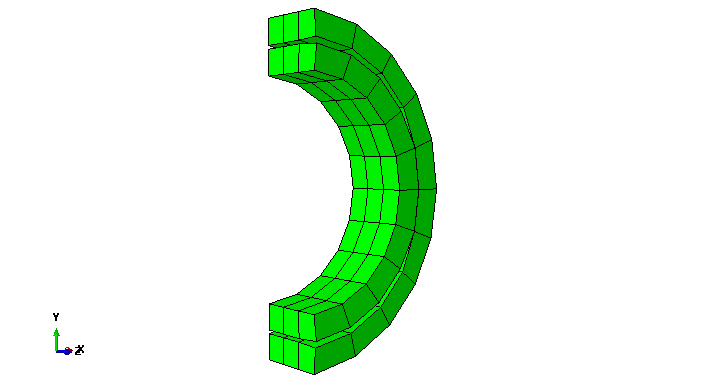
For the three-dimensional models illustrated in Figure 1.3.43–4 and Figure 1.3.43–5:
Step 1: The models consist of two parts with contact surfaces initially overclosed. This initial overclosure is resolved automatically in the step by using the automatic shrink fit capability in the contact interference definition.
Step 2: There are two places initially exposed to a fluid pressure with a magnitude of 20000; at the outside corner of the contact surfaces at the bottom end of the rings and along the whole edges of the contact surfaces at the upper end of the rings.
The contact pressure and the fluid pressure at each slave node on the contacting surfaces are output. Figure 1.3.43–6 specifically shows the deformation of the three-dimensional model in the middle of Step 2.
CPE4 elements.
CPE8 elements.
CAX4 elements.
CAX4 elements with a rigid body created from MAX1 elements.
CAX8 elements.
CAX8 elements.
CAX8 elements with a rigid body created from MAX1 elements.
CAX8 elements with a rigid body created from MAX1 elements.
SAX1 elements.
SAX1 elements with a rigid body created from SAX1 elements.
SAX2 elements.
SAX2 elements with a rigid body created from SAX1 elements.
C3D4 elements with an analytical rigid surface.
C3D6 elements with an analytical rigid surface.
C3D8 elements with an analytical rigid surface.
C3D10 elements with an analytical rigid surface.
C3D10M elements with an analytical rigid surface.
C3D15 elements with an analytical rigid surface.
C3D20 elements with an analytical rigid surface.
CCL9 elements with an analytical rigid surface.
CCL12 elements with an analytical rigid surface.
CCL18 elements with an analytical rigid surface.
CCL24 elements with an analytical rigid surface.
S4 elements with an analytical rigid surface.
SC6R elements with an analytical rigid surface.
SC8R elements with an analytical rigid surface.
M3D4 elements with an analytical rigid surface.
CPE4 elements.
CPE8 elements.
CPE8 elements.
CAX4 elements.
SAX1 elements.
SAX1 and CAX4 elements.
C3D4 elements.
C3D6 elements.
C3D8 elements.
C3D10 elements.
C3D10M elements.
C3D15 elements.
C3D20 elements.
CCL9 elements.
CCL12 elements.
CCL18 elements.
CCL24 elements.
S4 elements.
SC6R elements.
SC8R elements.
M3D4 elements.
CPE4 elements.
CAX4 elements.
C3D4 elements.
C3D8 elements.