Products: Abaqus/Explicit Abaqus/CAE
Surface property assignments:
can be used to change the contact thickness used for regions of a surface based on structural elements or to add a contact thickness for regions of a surface based on solid elements;
can be used to specify surface offsets for regions of a surface based on shell, membrane, rigid, and surface elements;
can be used to specify which edges of a model should be included in the general contact domain;
can be used to specify geometric corrections for regions of a surface;
can be applied selectively to particular regions within a general contact domain; and
cannot be applied to analytical rigid surfaces.
You can assign nondefault surface properties to surfaces involved in general contact interactions. These properties are considered only when the surfaces are involved in general contact interactions; they are not considered when the surfaces are involved in other interactions such as contact pairs. The general contact algorithm does not consider surface properties specified as part of the surface definition.
Surface property assignments propagate through all analysis steps in which the general contact interaction is active.
The surface names used to specify the regions with nondefault surface properties do not have to correspond to the surface names used to specify the general contact domain. In many cases the contact interaction will be defined for a large domain, while nondefault surface properties will be assigned to a subset of this domain. Any surface property assignments for regions that fall outside the general contact domain will be ignored. The last assignment will take precedence if the specified regions overlap.
| Input File Usage: | *SURFACE PROPERTY ASSIGNMENT, PROPERTY |
This option must be used in conjunction with the *CONTACT option. It should appear at most once per step for each value of the PROPERTY parameter discussed below; the data line can be repeated as often as necessary to assign surface properties to different regions. |
| Abaqus/CAE Usage: | Interaction module: Create Interaction: General contact (Explicit): Surface Properties |
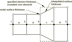
The default calculation of the nodal surface thickness (described in detail below) is appropriate for most analyses; one exception is sheet forming analysis, in which the thinning of a sheet significantly influences contact. This case can be modeled by specifying that the decreasing parent element thickness should be used. As a third alternative, you can specify a value for the surface thickness. A nonzero thickness can be assigned to solid element surfaces, for example, to model the effect of a finite-thickness surface coating. “Element-based surface definition,” Section 2.3.2, contains information on the spatial variation of the surface thickness.
Specifying the original or decreasing thickness results in a zero thickness for node-based surfaces; you can specify a nonzero thickness for a node-based surface used with the general contact algorithm (the contact pair algorithm will not consider a nonzero thickness for such surfaces).
The general contact algorithm requires that the contact thickness does not exceed a certain fraction of the surface facet edge lengths or diagonal lengths. This fraction generally varies from 20% to 60% based on the geometry of the element. The general contact algorithm will scale back the contact thickness automatically where necessary without affecting the thickness used in the element computations for the underlying elements. Diagnostic information is provided in the status (.sta) file if such scaling is performed.
To bypass this limitation on thickness, the contact surface can be modeled with surface elements (see “Surface elements,” Section 32.7.1). The surface elements must be attached to the underlying elements using a surface-based tie constraint (see “Mesh tie constraints,” Section 35.3.1), and a physically reasonable mass must be associated with the surface elements. This requires a significant fraction of the mass to be transferred to the surface elements from the underlying elements without appreciably altering the bulk mass properties. Alternatively, contact controls settings can be used to limit the thickness reduction checks (see “Contact controls for general contact in Abaqus/Explicit,” Section 36.4.5).
The “bull-nose” effect that occurs at shell perimeters with the contact pair algorithm (see “Assigning surface properties for contact pairs in Abaqus/Explicit,” Section 36.5.2) is avoided with the general contact algorithm by default. Shell element edges, nodes, and facets reflect the shell thickness in the normal direction only and do not extend past the perimeter. Contact controls settings can be used to turn off the bull-nose prevention checks (see “Contact controls for general contact in Abaqus/Explicit,” Section 36.4.5).
By default, the nodal thickness for surfaces based on shell, membrane, or rigid elements equals the minimum original thickness of the surrounding elements (see Figure 36.4.2–1 and Table 36.4.2–1).
Table 36.4.2–1 Thicknesses corresponding to Figure 36.4.2–1.
| Node | Element | Specified element thickness | Nodal surface thickness (minimum of adjacent element thicknesses) |
|---|---|---|---|
| 1 | 0.5 | ||
| a | 0.5 | ||
| 2 | 0.5 | ||
| b | 0.5 | ||
| 3 | 0.5 | ||
| c | 0.9 | ||
| 4 | 0.9 | ||
| d | 0.9 | ||
| 5 | 0.9 |
Figure 36.4.2–2 Small discrepancy between the nodal surface thickness and the specified nodal thickness.
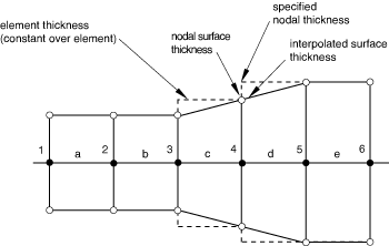
Table 36.4.2–2 Thicknesses corresponding to Figure 36.4.2–2.
| Node | Element | Specified nodal thickness | Element thickness (average of specified nodal thickness) | Nodal surface thickness (minimum of adjacent element thicknesses) |
|---|---|---|---|---|
| 1 | 0.5 | 0.5 | ||
| a | 0.5 | |||
| 2 | 0.5 | 0.5 | ||
| b | 0.5 | |||
| 3 | 0.5 | 0.5 | ||
| c | 0.7 | |||
| 4 | 0.9 | 0.7 | ||
| d | 0.9 | |||
| 5 | 0.9 | 0.9 | ||
| e | 0.9 | |||
| 6 | 0.9 | 0.9 |
| Input File Usage: | *SURFACE PROPERTY ASSIGNMENT, PROPERTY=THICKNESS surface, ORIGINAL (default) |
If the surface name is omitted, a default surface that encompasses the entire general contact domain is assumed. |
| Abaqus/CAE Usage: | Interaction module: Create Interaction: General contact (Explicit): Surface Properties: Shell/Membrane thickness assignments: Edit: Select surface, click the arrows to transfer surface to list of thickness assignments, and enter ORIGINAL in the Thickness column. |
If you specify that the decreasing parent element thickness should be used, only decreases in the parent element thickness are reflected in the contact surface thickness; if the parent element thickness actually increases during the analysis, the contact thickness will remain constant.
| Input File Usage: | *SURFACE PROPERTY ASSIGNMENT, PROPERTY=THICKNESS surface, THINNING |
If the surface name is omitted, a default surface that encompasses the entire general contact domain is assumed. |
| Abaqus/CAE Usage: | Interaction module: Create Interaction: General contact (Explicit): Surface Properties: Shell/Membrane thickness assignments: Edit: Select surface, click the arrows to transfer surface to list of thickness assignments, and enter THINNING in the Thickness column. |
You can directly specify the surface thickness value.
| Input File Usage: | *SURFACE PROPERTY ASSIGNMENT, PROPERTY=THICKNESS surface, value |
If the surface name is omitted, a default surface that encompasses the entire general contact domain is assumed. |
| Abaqus/CAE Usage: | Interaction module: Create Interaction: General contact (Explicit): Surface Properties: Shell/Membrane thickness assignments: Edit: Select surface, click the arrows to transfer surface to list of thickness assignments, and enter a value for the surface thickness magnitude in the Thickness column. |
You can apply a scale factor to any value of the surface thickness. For example, if you specify that the decreasing parent element thickness should be used for surf1 and apply a scale factor of 0.5, a value of one half the decreasing parent element thickness will be used for surf1 when it is involved in a general contact interaction (all other surfaces included in the general contact domain will use the default original parent element thickness). Scaling the surface thickness in this way can be used to avoid initial overclosures in some situations. Abaqus/Explicit will automatically adjust surface positions to resolve initial overclosures (see “Controlling initial contact status for general contact in Abaqus/Explicit,” Section 36.4.4). However, if nodal position adjustments are undesirable (for example, if they would introduce an imperfection in an otherwise flat part, resulting in an unrealistic buckling mode), you may prefer to reduce the surface thickness and avoid the overclosures entirely.
| Input File Usage: | *SURFACE PROPERTY ASSIGNMENT, PROPERTY=THICKNESS surface, value or label, scale_factor |
If the surface name is omitted, a default surface that encompasses the entire general contact domain is assumed. |
| Abaqus/CAE Usage: | Interaction module: Create Interaction: General contact (Explicit): Surface Properties: Shell/Membrane thickness assignments: Edit: Select surface, click the arrows to transfer surface to list of thickness assignments, and enter a Scale Factor. |
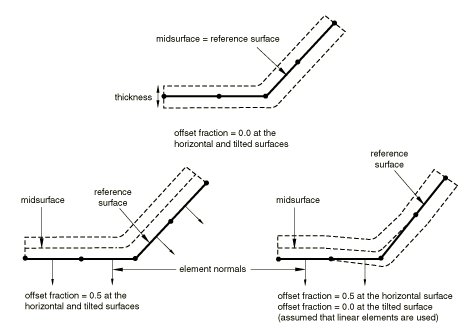
A surface offset is the distance between the midplane of a thin body and its reference plane (defined by the nodal coordinates and element connectivities). It is computed by multiplying the offset fraction (specified as a fraction of the surface thickness) by the surface thickness and the element facet normal. This defines the position of the midsurface and, thus, the position of the body with respect to the reference surface; the coordinates of the nodes on the reference surface are not modified. Surface offsets can be specified only for surfaces defined on shell and similar elements (i.e., membrane, rigid, and surface elements). Surface offsets specified for other elements (e.g., solid or beam elements) will be ignored. By default, surface offsets specified in element section definitions will be used in the general contact algorithm.
The surface offset at each node is the average of the maximum and minimum offsets among the faces connected to the node. The offset at a point within a facet is interpolated from the nodal values. Figure 36.4.2–3 shows some examples of the positioning of the contact surface with respect to the reference surface for various combinations of surface offsets. Surface offsets used in the general contact algorithm are constrained to lie between 0.5 and 0.5 of the thickness.
You specify the surface offset as a fraction of the surface thickness. The surface offset fraction can be set equal to the offset fraction used for the surface's parent elements or to a specified value. Surface offsets specified for general contact do not change the element integration.
| Input File Usage: | Use the following option to use the surface offset fraction from the surface's parent elements (default): |
*SURFACE PROPERTY ASSIGNMENT, PROPERTY=OFFSET FRACTION
surface, ORIGINAL
Use the following option to specify a value for the surface offset fraction: *SURFACE PROPERTY ASSIGNMENT, PROPERTY=OFFSET FRACTION surface, offset The offset can be specified as a value or a label (SPOS or SNEG). Specifying SPOS is equivalent to specifying a value of 0.5; specifying SNEG is equivalent to specifying a value of 0.5. |
| Abaqus/CAE Usage: | Interaction module: Create Interaction: General contact (Explicit): Surface Properties: Shell/Membrane offset assignments: Edit: Select surface, and click the arrows to transfer surface to list of offset assignments. In the Offset Fraction column, enter ORIGINAL to use the surface offset fraction from the surface's parent elements, enter SPOS to use a surface offset fraction of 0.5, enter SNEG to use a surface offset fraction of 0.5, or enter a value for the surface offset fraction. |
Feature edges of a model are defined on beam and truss elements and edges of faces (perimeter and otherwise) of solid and structural elements. By default, edge-to-edge contact in the general contact algorithm in Abaqus/Explicit accounts for perimeter edges as well as “contact edges” of beam and truss elements.
You can control which feature edges should be activated in the general contact domain by specifying feature edge criteria. By default, only perimeter edges are activated. Feature edge criteria have no effect on “edges” of beam and truss elements—they are activated by their inclusion in the contact domain.
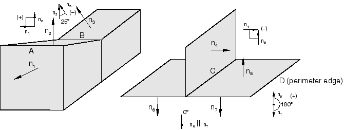
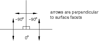
The feature angle is the angle formed between the normals of the two facets connected to an edge. The angles between facets are based on the initial configuration. A negative angle will result at concave meetings of facets; therefore, these edges are never included in the contact domain. Figure 36.4.2–4 shows some examples of how the feature angle is calculated for different edges.
The feature angle for edge A is 90° (the angle betweenFigure 36.4.2–5 Feature angles for a T-intersection (for example, edge C in Figure 36.4.2–4).
The sign of the feature angle is considered when determining whether or not a geometric feature edge should be activated in the general contact domain. For example, if a cutoff feature angle of 20° were specified, edge A would be activated as a feature edge in the contact model (90° > 20°) but edges B and C would not be activated: 25° < 20° and 0° (the maximum feature angle for edge C) < 20°.
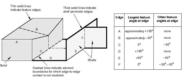
Figure 36.4.2–6 illustrates further how the feature angle is used to determine which geometric feature edges should be activated in the general contact domain.
The table to the right of the figure lists the feature angle values for various edges in the model. Edges connected to more than two facets, as well as edges connected to two shell facets, have more than one corresponding feature angle. The largest feature angle at an edge is compared to the specified cutoff feature angle. For example, if a cutoff feature angle of 20° were specified, edges A, D, and E would be considered feature edges, while edges B, C, and F would be ignored for edge-to-edge contact.By default, only perimeter edges are included in the general contact domain. Perimeter edges occur on “physical” perimeters of shell elements and on “artificial” edges that occur when a subset of exposed facets on a body are included in the general contact domain. When structural elements share nodes with continuum elements, the perimeter edges will not be activated on the structural elements because the criterion to designate them as such is no longer satisfied.
| Input File Usage: | *SURFACE PROPERTY ASSIGNMENT, PROPERTY=FEATURE EDGE CRITERIA surface, PERIMETER EDGES (default) |
If the surface name is omitted, a default surface that encompasses the entire general contact domain is assumed. |
| Abaqus/CAE Usage: | Interaction module: Create Interaction: General contact (Explicit): Surface Properties: Feature edge criteria assignments: Edit: Select surface, click the arrows to transfer surface to list of feature assignments, and enter PERIMETER in the Feature Edge Criteria column. |
You can choose particular feature edges on surface, structural, and rigid elements to be activated in domain. A surface containing a list of element labels and edge identifiers (see “Defining edge-based surfaces” in “Element-based surface definition,” Section 2.3.2) is used to specify the edges to activate.
| Input File Usage: | *SURFACE PROPERTY ASSIGNMENT, PROPERTY=FEATURE EDGE CRITERIA surface, PICKED EDGES |
| Abaqus/CAE Usage: | Interaction module: Create Interaction: General contact (Explicit): Surface Properties: Feature edge criteria assignments: Edit: Select the surface, click the arrows to transfer the surface to the list of feature assignments, and enter PICKED in the Feature Edge Criteria column. |
You can choose to activate all edges in a given surface in the general contact domain. This will activate all edges of every face specified in the given surface.
| Input File Usage: | *SURFACE PROPERTY ASSIGNMENT, PROPERTY=FEATURE EDGE CRITERIA surface, ALL EDGES |
| Abaqus/CAE Usage: | Interaction module: Create Interaction: General contact (Explicit): Surface Properties: Feature edge criteria assignments: Edit: Select the surface, click the arrows to transfer the surface to the list of feature assignments, and enter ALL in the Feature Edge Criteria column. |
You can choose to deactivate all feature edges (including perimeter edges) in the general contact domain. This option does not deactivate “contact edges” associated with beam and truss elements.
| Input File Usage: | *SURFACE PROPERTY ASSIGNMENT, PROPERTY=FEATURE EDGE CRITERIA surface, NO FEATURE EDGES |
If the surface name is omitted, a default surface that encompasses the entire general contact domain is assumed. |
| Abaqus/CAE Usage: | Interaction module: Create Interaction: General contact (Explicit): Surface Properties: Feature edge criteria assignments: Edit: Select the surface, click the arrows to transfer the surface to the list of feature assignments, and enter NONE in the Feature Edge Criteria column. |
If you specify a cutoff feature angle as the feature edge criteria, perimeter edges and geometric edges with feature angles greater than or equal to the specified angle are activated in the general contact domain. As described previously, you can activate additional feature edges if needed.
| Input File Usage: | *SURFACE PROPERTY ASSIGNMENT, PROPERTY=FEATURE EDGE CRITERIA surface, feature_angle_value |
If the surface name is omitted, a default surface that encompasses the entire general contact domain is assumed. |
| Abaqus/CAE Usage: | Interaction module: Create Interaction: General contact (Explicit): Surface Properties: Feature edge criteria assignments: Edit: Select surface, click the arrows to transfer surface to list of feature assignments, and enter a value for the cutoff feature angle (in degrees) in the Feature Edge Criteria column. |
You can assign a different feature edge criteria to different regions of the general contact domain. For example, Table 36.4.2–3 and Table 36.4.2–4 show the input that could be used to specify that none of the feature edges of surf1, only perimeter edges of surf2, and perimeter edges and feature edges of surf3 with a feature angle greater than 30° should be considered for edge-to-edge contact.
To cut down on the computational cost in certain situations, it may be desirable to identify a limited number of feature edges on a surface (presumably at locations where there are sharp gradients in the surface normals) as “primary” feature edges. A more relaxed criterion can be used to denote certain other edges on the surface as “secondary” feature edges. If secondary feature edges are specified in addition to primary feature edges, Abaqus/Explicit enforces edge-to-edge contact between primary feature edges and between primary feature edges and secondary feature edges only. Edge-to-edge contact is not enforced between secondary feature edges. This ensures that interpenetrations are avoided at locations where there are “true” edges in the model, without the need to activate primary feature edges at locations where the gradients in the surface normals are only moderate. A judicious choice of criteria for selecting primary and secondary feature edges can lead to significant savings in computational costs.
Secondary feature edges can be selected for a surface by specifying a secondary feature edge criterion in addition to the criterion used to select the primary feature edges for that surface. If the secondary feature edge criterion is omitted, only primary feature edges are activated for the surface. Allowable criteria for secondary feature edges are:
all edges that have not been selected as primary feature edges;
all picked edges that have not been selected as primary feature edges;
all perimeter edges that have not been selected as primary feature edges; and
all edges with a feature angle greater than a specified cutoff angle value that have not been selected as primary feature edges.
The allowable values for the secondary feature edge criterion permit possible combinations of criteria for primary feature edges and secondary feature edges, shown in Table 36.4.2–5.
Table 36.4.2–5 Valid combinations of primary feature edge and secondary feature edge criteria.
| Primary Feature Edge Criterion | Secondary Feature Edge Criterion |
|---|---|
| No feature edges | All remaining edges, picked edges, perimeter edges, cutoff angle |
| All edges | Any criterion specified for secondary feature edges will be ignored |
| Picked edges | All remaining edges, perimeter edges, cutoff angle |
| Perimeter edges | All remaining edges, picked edges, cutoff angle |
| Cutoff angle | All remaining edges, picked edges, perimeter edges, cutoff angle |
You can specify that all edges belonging to the surface that have not been selected as primary feature edges become secondary feature edges.
| Input File Usage: | *SURFACE PROPERTY ASSIGNMENT, PROPERTY=FEATURE EDGE CRITERIA surface, primary feature edge criterion, ALL REMAINING EDGES |
If the surface name is omitted, a default surface that encompasses the entire general contact domain is assumed. |
| Abaqus/CAE Usage: | Secondary feature edges are not supported in Abaqus/CAE. |
You can specify that all picked edges of the surface that have not already been selected as primary feature edges become secondary feature edges.
| Input File Usage: | *SURFACE PROPERTY ASSIGNMENT, PROPERTY=FEATURE EDGE CRITERIA surface, primary feature edge criterion, PICKED EDGES |
If the surface name is omitted, a default surface that encompasses the entire general contact domain is assumed. |
| Abaqus/CAE Usage: | Secondary feature edges are not supported in Abaqus/CAE. |
You can specify that all perimeter edges of the surface that have not already been selected as primary feature edges become secondary feature edges.
| Input File Usage: | *SURFACE PROPERTY ASSIGNMENT, PROPERTY=FEATURE EDGE CRITERIA surface, primary feature edge criterion, PERIMETER EDGES |
If the surface name is omitted, a default surface that encompasses the entire general contact domain is assumed. |
| Abaqus/CAE Usage: | Secondary feature edges are not supported in Abaqus/CAE. |
You can specify that edges on the surface with a feature angle greater than the specified value that have not been selected as primary feature edges become secondary feature edges. If an angle value has also been specified for primary feature edges, the angle value specified for secondary feature edges must be smaller than the value specified for primary edges.
| Input File Usage: | *SURFACE PROPERTY ASSIGNMENT, PROPERTY=FEATURE EDGE CRITERIA surface, primary feature edge criterion, feature_angle_value |
If the surface name is omitted, a default surface that encompasses the entire general contact domain is assumed. |
| Abaqus/CAE Usage: | Secondary feature edges are not supported in Abaqus/CAE. |
For a particular surface you may not want to activate any primary feature edges; instead, you might want to activate all or some edges on the surface as secondary feature edges (to enforce contact between these secondary feature edges and primary feature edges on another surface in the model). In that case you can specify that no feature edges should be activated as the primary feature edge criterion for the surface, while using any criterion of choice for the secondary feature edges.
| Input File Usage: | *SURFACE PROPERTY ASSIGNMENT, PROPERTY=FEATURE EDGE CRITERIA surface, NO FEATURE EDGES, secondary feature edge criterion |
If the surface name is omitted, a default surface that encompasses the entire general contact domain is assumed. |
| Abaqus/CAE Usage: | Secondary feature edges are not supported in Abaqus/CAE. |
By default, contact calculations are based on unsmoothed, faceted representations of the finite element surfaces in a general contact domain. Discrepancies between the true surface geometry and the faceted surface geometry may result in significant noise in the solution. Optional contact smoothing techniques simulate a more realistic representation of curved surfaces in the contact calculations. These techniques allow a discretized surface with discontinuous surface normals to more closely approximate the behavior of a smooth surface during an analysis. Improvements to results with the surface correction include more accurate contact stresses and less solution noise upon relative sliding between contact surfaces.
Contact smoothing can be specified for surfaces in a general contact domain using a surface property assignment. A single surface property assignment specifies all of the surfaces to be smoothed, as well as the appropriate geometry correction method for each surface. Three geometry correction methods can be employed:
The circumferential smoothing method is applicable to surfaces approximating a portion of a surface of revolution.
The spherical smoothing method is applicable to surfaces approximating a portion of a sphere.
The toroidal smoothing method is applicable to surfaces approximating a portion of a torus (i.e., a circular arc revolved about an axis).
For each surface, you must specify the appropriate geometry correction method and either the approximate axis of revolution (for circumferential or toroidal smoothing) or the approximate spherical center (for spherical smoothing). For toroidal smoothing, you must also specify the distance of the center of the circular arc from the axis of revolution, and the line joining point (Xa, Ya, Za) and the center of the circular arc should be perpendicular to the axis of revolution.
| Input File Usage: | Use the following option to apply a geometric correction: |
*SURFACE PROPERTY ASSIGNMENT, PROPERTY=GEOMETRIC CORRECTION data lines to define smoothing regions (see below) Use the following data line to apply circumferential smoothing to a surface with an axis of symmetry passing through points (Xa, Ya, Za) and (Xb, Yb, Zb): surface, CIRCUMFERENTIAL, Xa, Ya, Za, Xb, Yb, Zb Use the following data line to apply spherical smoothing to a surface with a spherical center at point (Xa, Ya, Za): surface, SPHERICAL, Xa, Ya, Za Use the following data line to apply toroidal smoothing to a surface with an axis of symmetry passing through points (Xa, Ya, Za) and (Xb, Yb, Zb) with the center of the revolved circular arc at a distance R from the axis of symmetry: surface, TOROIDAL, Xa, Ya, Za, Xb, Yb, Zb, R Repeat the data lines as many times as necessary to define the appropriate geometry corrections for all surfaces in the contact domain. |
| Abaqus/CAE Usage: | Contact surface smoothing can be applied only to native geometry models in Abaqus/CAE. Abaqus/CAE can automatically detect all circumferential, spherical, and toroidal surfaces in the general contact domain that can be smoothed and apply the appropriate smoothing. |
Use the following option to enable automatic surface smoothing of a model: Interaction module: Create Interaction: General contact (Explicit): Surface Properties: Surface smoothing assignments: Edit: toggle on Automatically assign smoothing for geometric faces Use the following option to manually apply smoothing to a surface: Interaction module: Create Interaction: General contact (Explicit): Surface Properties: Surface smoothing assignments: Edit: Select the surface, click the arrows to transfer the surface to the list of smoothing assignments. In the Smoothing Option column, select REVOLUTION to apply circumferential smoothing, select SPHERICAL to apply spherical smoothing, select TOROIDAL to apply toroidal smoothing, or select NONE to prevent smoothing of the surface. |
The contact smoothing technique assumes that the initial locations of the surface nodes lie on the true initial surface geometry, with the exception of midedge nodes of C3D10M elements. This smoothing technique remains effective even if the midedge nodes of C3D10M elements do not lie on the true initial geometry (models meshed using Abaqus/CAE always have midedge nodes placed on the true initial geometry, but this may not be the case with other meshing preprocessors).
The effects of contact smoothing tend to be most significant for analyses involving small deformation, and the smoothing technique works well for cases involving large relative motion between the surfaces. For analyses with large deformation this smoothing technique typically has an insignificant effect on the solution. However, in some cases—especially where the underlying elements can fail—the smoothing can degrade the solution accuracy after large deformation.
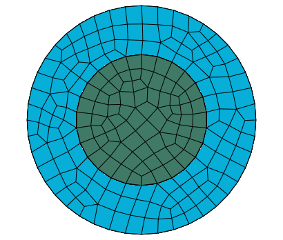
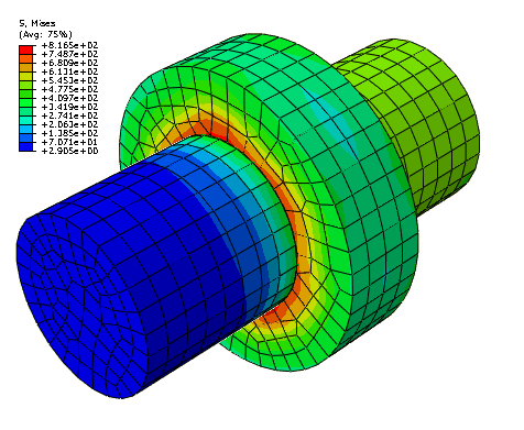
The impact of contact surface smoothing can be demonstrated by a simple model of contact between concentric cylinders with a small clearance between them. With a matched mesh as shown in Figure 36.4.2–7 there are no initial overclosures; therefore, there are no initial strain-free initial displacement adjustments. However, if the inner cylinder is rotated, the cylinders develop stresses (see Figure 36.4.2–8) as contact is detected due to the linear faceted representation of the master surface. This behavior is improved when the circumferential smoothing technique is applied to the contacting surfaces of the two cylinders.