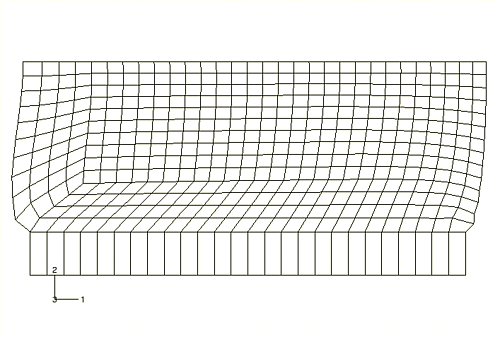
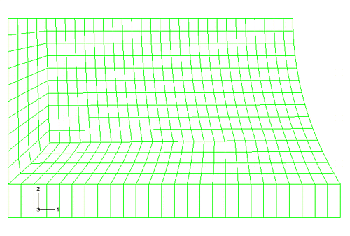
We know that the element distortions in the corners of the rubber mount are undesirable. The results in these areas are unreliable; and if the load were increased, the analysis might fail. These problems can be corrected by using a better mesh design. The mesh shown in Figure 10–67 is an example of an alternate mesh design that might be used to reduce element distortion in the bottom left corner of the rubber model.
Figure 10–67 Modified mesh to minimize element distortions in the bottom left corner of the rubber model during the simulation.
The contours of maximum principal stress (Figure 10–69) show that the very localized stress in that corner has been reduced only slightly.
Mesh design for large-distortion problems is more difficult than it is for small-displacement problems. A mesh must be produced where the shape of the elements is reasonable throughout the analysis, not just at the start. You must estimate how the model will deform using experience, hand calculations, or the results from a coarse finite element model.