Products: Abaqus/Standard Abaqus/CAE
This example uses the Optimization module to minimize the weight of a car door by changing the thickness of the sheet metal components while limiting the vertical displacement (sag) of the door relative to its encastered hinges.
The example also constrains the first frequency mode of the door to be higher than a specified value to avoid resonance triggered by engine vibration while maintaining its strength against the vertical load. The optimization takes into account geometric restrictions imposed by constraints in the manufacturing process and by constraints in design aesthetics. This model has been developed by The National Crash Analysis Center (NCAC) of The George Washington University under a contract with the Federal Highway Administration (FHWA) and the National Highway Traffic Safety Administration (NHTSA) of the United States Department of Transportation (US DOT).
This example illustrates sizing optimization of the sheet metal components that form a car door. Sizing optimization modifies the thickness of the shell elements in the design area to achieve the optimized solution. Clustering is applied during the sizing optimization, which forces elements in selected regions to have the same shell thickness and reproduces the real-world assembly of sheet metal components by layering parts of uniform thickness. A “free” sizing optimization of the same model generates a door that weighs less than the result of the clustered sizing optimization; however, the resulting element-by-element distribution of shell thickness would be impossible to reproduce on the production line. For more information, see “Sizing optimization” in “Structural optimization: overview,” Section 13.1.1 of the Abaqus Analysis User's Guide.
The door assembly is composed of the single orphan mesh part derived from the data supplied by the NCAC. The connections, contact definitions, and step definitions were converted to follow best practices in Abaqus. For example, regions (element sets) within the model are joined by spot welds (mesh-independent fasteners). The two hinges are modeled with hinge connectors and kinematic couplings. The door lock is modeled with a kinematic coupling.
Three materials are used to form the door—glass, plastic, and steel. The glass material properties are assigned to the element set representing the window. The plastic material properties are assigned to the element sets representing the inserts in the door trim, such as the liner. The steel material properties are assigned to the element sets representing the sheet metal door and its hinges and brackets. The material properties assumed for this analysis are shown in Table 11.3.2–1, Table 11.3.2–2, and Table 11.3.2–3. The symbols ![]() ,
, ![]() , and
, and ![]() , represent the Young's modulus, Poisson's ratio, and density, respectively.
, represent the Young's modulus, Poisson's ratio, and density, respectively.
Elastic material properties are sufficient because the small load that is applied to model vertical door sag is insufficient to cause plastic or permanent deformation.
Two load cases are applied to the model:
a Lanczos solver frequency step that determines the first five eigenvalues, and
a static load step that determines how much the door sags in response to a vertical load on the door lock.
The sizing optimization is configured as described in the following sections.
The entire car door, except for the plastic trim, is selected as the design area of the model.
The example includes three design responses:
a weight design response that is applied to the entire assembly,
an eigenfrequency design response that uses the default modal analysis formulation (Lanczos), and
a displacement design response that is applied only to the door lock.
A constraint in the frequency step restricts the first eigenfrequency from falling below a value that would trigger resonance with engine vibration at idle speed (35 Hz). A constraint in the static load step restricts the absolute displacement of the door lock in the z-direction to be less than or equal to a reasonable value (1.42 mm).
The thickness of the element sets representing the sheet metal parts is restricted to a reasonable range (0.5 < thickness < 2.5). Frozen area geometric restrictions force the element sets representing the window and the hinges and their brackets to remain unchanged during the optimization. In addition, the design of the exterior-facing door panel has been finalized by the styling department, and a frozen area geometric restriction prevents changes in thickness to the elements that form the outside of the door.
This example imports the model in the form of an orphan mesh from an input file. The input file contains the element sets that are used to define the regions of the model that are used by the optimization, such as the window and the hinges and their brackets. The example creates an optimization process that you can submit for analysis.
Most of the door is meshed with quadrilateral regions that are assigned S4R three-dimensional shell elements, and the small number of triangular regions are assigned S3R elements. In addition, the three-dimensional solid region that represents the arm rest is assigned C3D4, C3D6, and C3D8R three-dimensional solid elements. The sizing optimization operates only on shell elements.
An input file (door.inp) defines the nodes and elements that define the door along with the element sets that represent the regions of the door. The input file also defines the kinematic couplings, multi-point constraints, and spot weld connections. A Python script (door_sizing_optimization_w_clustering.py) is included that imports the input file and builds the optimization model. The scripts can be run interactively or from the command line. The Python script and the input file must be available from your working directory.
To run the optimization, you can submit the optimization process from the Optimization Process Manager in the Job module. You can use the Optimization Process Manager to monitor the progression of the optimization. In addition, when the optimization process is complete, you can use the Optimization Process Manager to combine the output from the optimization into a single output database file that can be viewed in the Visualization module.
A maximum number of 15 design cycles is specified; however, the optimization process converges over nine design cycles. The convergence criterion for a sizing optimization is based on a combination of the change of the element thickness and the change in the value of the objective function. Minimizing the weight is the objective function, and the total weight is reduced by 14% (from 30.6 kg to 26.3 kg) while satisfying the eigenfrequency and door sag constraints.
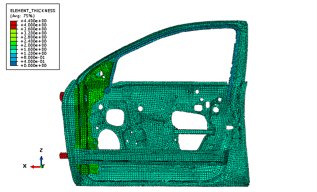
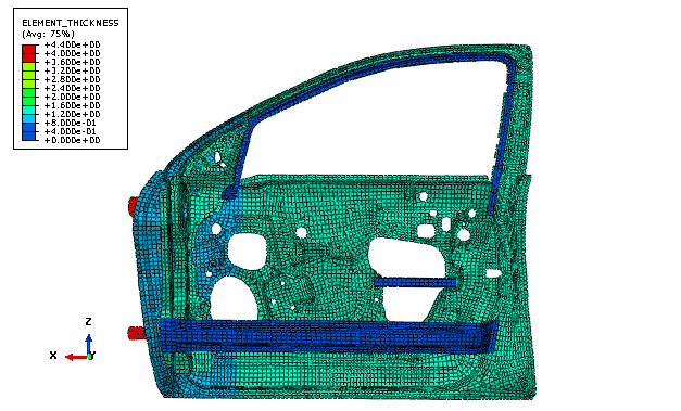
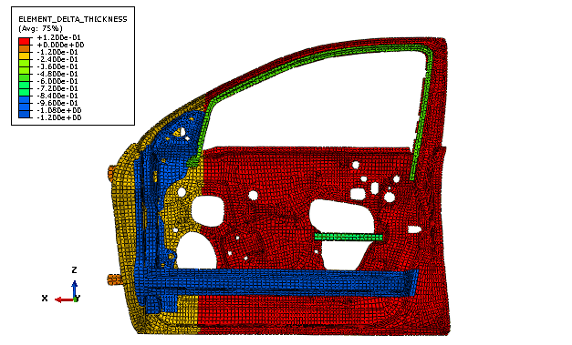
Figure 11.3.2–1 shows the initial element thickness at the end of the second step prior to any optimization. Figure 11.3.2–2 and Figure 11.3.2–3 show the results of the sizing optimization—the value of the absolute shell thickness and the change in shell thickness. Regions of the model that take no part in the optimization, such as the plastic liner, have been removed from the figures to make the output easier to understand.
Script to import the input file (door.inp) and to build the optimization model.
Orphan mesh representation of the car door assembly; and the node and element set, material, load, boundary condition, and connector definitions that are used by the optimization.
Svanberg, K., The Method of Moving Asymptotes—A New Method for Structural Optimization International Journal for Numerical Methods in Engineering, Vol. 24, pp. 359–373, 1987.
This model has been developed by The National Crash Analysis Center (NCAC) of The George Washington University under a contract with the Federal Highway Administration (FHWA) and the National Highway Traffic Safety Administration (NHTSA) of the United States Department of Transportation (US DOT).