Product: Abaqus/Standard
This example illustrates the effect of coupling between a structure and an acoustic medium.
Coupling between a structure and an acoustic medium can produce problems when the solid-fluid interaction is fundamental to the overall vibrational behavior of the body or of the acoustic fluid. Typical examples of such problems include loudspeaker enclosures, fluid-filled tanks, muffler systems, and vehicle cabin enclosures.
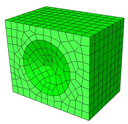
The model is shown in Figure 9.1.2–1. The system considered here consists of a speaker box, a speaker cone, and the interacting interior. To simplify the problem, the effect of interacting air at the outside of the speaker box is neglected. The width, depth, and height of the speaker box are 0.5 m, 0.4 m, and 0.6 m, respectively. Its thickness is 0.005 m. The speaker box is made of wood with a Young's modulus, E, of 11.6 GPa; a Poisson's ratio, ![]() , of 0.3; and a density,
, of 0.3; and a density, ![]() , of 562 kg/m3. At the center of the front speaker box, there is a cone-shaped speaker 0.345 m in diameter, 0.04 m in height, and 0.001 m in thickness. No mass or impedance of the speaker is considered. The speaker is made of polyethylene with a Young's modulus, E, of 3.4 GPa; a Poisson's ratio,
, of 562 kg/m3. At the center of the front speaker box, there is a cone-shaped speaker 0.345 m in diameter, 0.04 m in height, and 0.001 m in thickness. No mass or impedance of the speaker is considered. The speaker is made of polyethylene with a Young's modulus, E, of 3.4 GPa; a Poisson's ratio, ![]() , of 0.3; and a density,
, of 0.3; and a density, ![]() , of 450 kg/m3. The air has a density,
, of 450 kg/m3. The air has a density, ![]() , of 1.11 kg/m3 and a bulk modulus,
, of 1.11 kg/m3 and a bulk modulus, ![]() , of 0.134 MPa. Volumetric drag of the air is assumed to have a negligible effect in this problem, so it is ignored in this analysis.
, of 0.134 MPa. Volumetric drag of the air is assumed to have a negligible effect in this problem, so it is ignored in this analysis.
First-order hexahedral acoustic elements (AC3D8) and first-order acoustic triangular prism elements (AC3D6) are used to fill in the volume of the interior air region. The speaker box and speaker are meshed with S4R and S3R elements, respectively. No mesh convergence study has been done since the example is intended only as an illustration. The choice of mesh density (element size) is discussed in “Acoustic, shock, and coupled acoustic-structural analysis,” Section 6.10.1 of the Abaqus Analysis User's Guide.
The surface-based tie constraint is used to couple the structure with the air inside. Surfaces are defined at the inside of the speaker box and the speaker cone and at the free surface of the air. To constrain the structure, four corner points of the bottom panel are simply supported.
A substructure analysis is performed as well. The entire speaker model is turned into a dynamic coupled structural-acoustic substructure using all the eigenmodes up to 800 Hz. A substructure load case is generated to be used in the forced response analyses.
The results for each of the analyses are discussed below.
If the eigenvalues of the structure alone or the acoustic medium alone are not in the range of interest, it is not necessary to consider the whole system simultaneously. Thus, it is recommended that you understand the modal characteristics of each part separately before analyzing the whole system. The eigenfrequency extraction procedure takes acoustic-structural coupling effects into account by default if an acoustic medium and a structure are joined using a tie constraint. To ignore this effect, you can compute uncoupled mode sets for acoustic and structural/solid regions using the eigenfrequency extraction procedure or perform an eigenvalue extraction analysis that uses the SIM architecture.
In the SIM-based analysis, uncoupled modes are extracted and the structural-acoustic coupling is imposed in the subsequent modal steady-state dynamic procedure. To compensate for the approximation introduced by using uncoupled modes, the maximum frequency of interest for acoustic modes is increased by setting the acoustic range factor to a value greater than 1.0. In addition, residual modes are requested to reduce the modal truncation error. To request residual modes in the Lanczos eigensolver, you must first compute the static perturbation response of the load that will be applied in the subsequent mode-based analysis by specifying that load in a static perturbation step that immediately precedes the frequency extraction step. The residual modes are computed in both the coupled and uncoupled eigenvalue extraction analyses.
The results of the natural frequency analysis of the uncoupled system are summarized in Table 9.1.2–1. The natural frequencies for both the structure and the air span the same range in this example, which shows that the two parts can affect each other. Thus, the coupled approach should be adopted to understand the characteristics of the whole speaker system in this example.
Table 9.1.2–2 shows the results of the natural frequency analysis of the coupled system. Due to the coupling effect, the eigenfrequencies shift mode by mode. Each mode shape is also more complex than those in the uncoupled case, so that each mode has nonzero components on both the structural and acoustic parts. The substructure analysis based on coupled modes yields eigenfrequencies identical to those from the analysis without substructures.
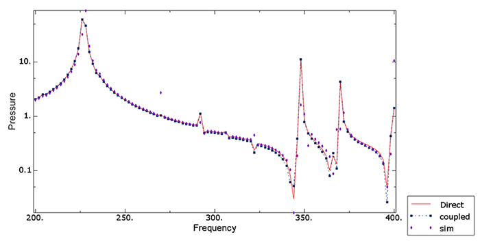
The response of the system is obtained by using mode-based and direct-solution steady-state dynamic analyses. The eigenvalue extraction analysis must be performed prior to the modal analysis. Two types of mode-based steady-state dynamic analyses are performed: an analysis that is based on coupled modes and a SIM-based analysis that utilizes uncoupled modes. The analyses are performed as frequency sweeps from 200 to 400 Hz. The system is excited by a concentrated force of 1.0 N at the center point of the speaker cone. The results for the coupled frequency response using each of the three methods are shown in Figure 9.1.2–2. This figure illustrates the acoustic pressure near the center point of the speaker cone, plotted as a function of frequency. The results for the mode-based steady-state dynamic analyses based on coupled and uncoupled modes show good agreement with the direct-solution steady-state dynamic results. Because the coupling between the structure of the speaker and the air inside is relatively strong, additional acoustic eigenmodes are extracted for the modal analysis based on uncoupled modes to improve accuracy. The substructure analysis produces results that are virtually identical to the results from the equivalent analysis without substructures.
Direct-solution steady-state dynamic analysis.
Natural frequency extraction of coupled eigenmodes and mode-based steady-state dynamic analysis using coupled modes.
Natural frequency extraction of uncoupled eigenmodes and mode-based steady-state dynamic analysis using uncoupled modes.
Substructure generation for the coupled structural-acoustic model and steady-state dynamic solution without substructure.
Direct-solution and mode-based steady-state dynamic analyses using the substructure.
Mode-based steady-state dynamic analysis using uncoupled eigenmodes extracted with the AMS eigensolver.
Model definition.
Table 9.1.2–1 Uncoupled frequency analysis. Modes are arranged in order of increasing frequency starting from 201 Hz.
| Mode | Frequency [Hz] | Description |
|---|---|---|
| 1 | 201 | Structure |
| 2 | 211 | Structure |
| 3 | 212 | Structure |
| 4 | 232 | Structure |
| 5 | 247 | Structure |
| 6 | 263 | Structure |
| 7 | 283 | Air |
| 8 | 283 | Structure |
| 9 | 313 | Structure |
| 10 | 314 | Structure |
| 11 | 339 | Air |
| 12 | 352 | Structure |
| 13 | 361 | Structure |
| 14 | 382 | Structure |
Table 9.1.2–2 Coupled frequency analysis. Modes are arranged in order of increasing frequency starting from 204 Hz.
| Mode | Frequency [Hz] | Description |
|---|---|---|
| 1 | 204 | Coupled mode |
| 2 | 227 | Coupled mode |
| 3 | 228 | Coupled mode |
| 4 | 235 | Coupled mode |
| 5 | 245 | Coupled mode |
| 6 | 269 | Coupled mode |
| 7 | 292 | Coupled mode |
| 8 | 307 | Coupled mode |
| 9 | 322 | Coupled mode |
| 10 | 348 | Coupled mode |
| 11 | 352 | Coupled mode |
| 12 | 367 | Coupled mode |
| 13 | 370 | Coupled mode |
| 14 | 399 | Coupled mode |